|
Product Details:
Payment & Shipping Terms:
|
Product Name: | OBP System | Wavelength: | 1310&1550nm |
---|---|---|---|
Network Interface: | RJ45/RS-232( Or RS-485 ) | Connector: | SC/PC |
Optical Power Range: | -50 ~ +23 DBm | Size: | 19" 1U |
Highlight: | ADM Optical Bypass Protection Switch,1550nm Optical Bypass Protection Switch,5W Optical Fiber Protection Switch |
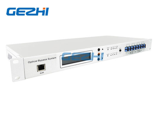
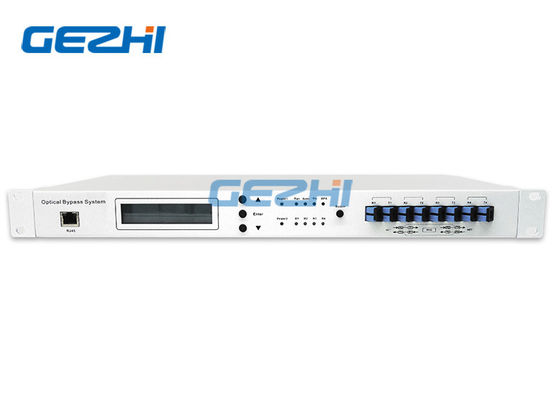
Optical Bypass Protection Switch in Optical fiber protection for ADM
In some network topologies, failure of network equipment or power outages may have an impact not only on traffic that terminates at these nodes but also on the rest of the network. The most effective solution for such scenarios are Bypass systems that allow traffic to bypass failed nodes.
Optical Bypass Protection is a kind of intelligent optical switch system which can bypass fault node in optical transmission network to avoid breakdown of whole network communication. It can automatically switch when detects the node’s power-down or signal failure.
Technical Parameter
Parameters | Unit | |
Switching Time | ms | < 30 |
Standardizing Wavelength | nm | 1310 & 1550 |
Optic Power Range | dBm | -50 ~ +23 dBm |
Optical Power Accuracy | ± 5% | |
Insertion Loss | dB | <1.5 |
Crosstalk | dB | > 50 |
Return Loss | dB | > 45 |
Max Power Tolerance | mw | 300 |
Power Consumption | W | < 5 |
Optical Connectors | SC/PC | |
Network Interface | RJ45/RS-232( or RS-485 ) | |
Operating Temperature | ℃ | -10 ~ 55 |
Storage Temperature | ℃ | -20 ~ 70 |
Power Supply | DC:36 ~ 72V | |
AC:85 ~ 264V | ||
Case | 19' 1U |
Features
Independent of data rate, format and wavelength.
Highly configurable to fit network applications.
Simple, plug-and-play Installation.
User-selectable revertive and non-revertive modes.
Latching optical switch.
Front panel LED and remote alarm.
Application
Optical fiber protection for ADM transmission in any data format.
Optical dedicated protection for fiber ring.
Optical bypass protection switch provides both Manual and Automatic switching mode. In Manual mode, the system switches optical path only based on the commands from user. In the Automatic mode, the system switches based on the power level detected and the preset threshold. Under automatic mode, the system can be set to be Revertive or Non-revertive modes. Under Revertive mode, the system switches back to the working path automatically after the fault condition is cleared. Under Non-revertive mode, the system does not switch back.
While the need for bypass protection is intuitive in linear networks, other topologies may benefit from it as well. One case is ring networks, whose self-healing capacity is limited to a single failure. A ring-topology network can recover from a single fiber cut or failure of a single node: traffic terminated at a failed node is lost, but the rest of the network continues to function. In some cases, such as metro networks that are subject to floods and power outages, multiple concurrent failures are likely and the ring’s inherent resilience is insufficient. Using a bypass switch at each node offers protection from multiple failures, bypassing all of the failed nodes so even in multi-node failure situation the ring will maintain its self-healing operation. Figure shows how bypass systems can protect a ring from multiple failures.
Contact Person: Ena Lin
Tel: +86-13544277727